• 1
  • 2
  • 3
  • 4

What are TVS Diodes?

  What are TVS Diodes?

  By Kelvin Tan

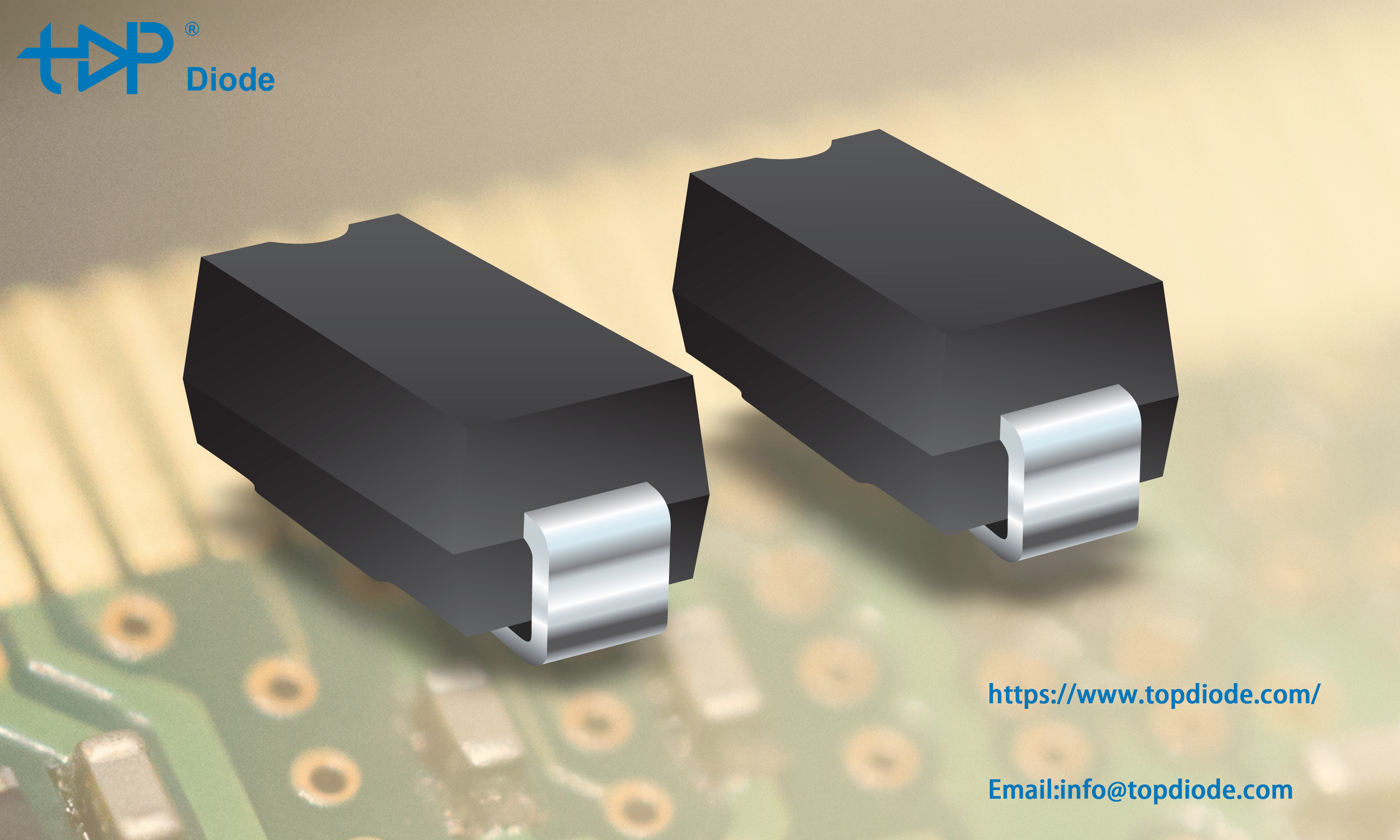
  TVS Diodes are electronic components designed to protect sensitive electronics from high-voltage transients. They can respond to overvoltage events faster than most other types of circuit protection devices, and are offered in a variety of surface mount and through-hole circuit board mounting formats.

  They function by limiting voltage to a certain level (referred to as a "clamping" device) with p-n junctions that have a larger cross-sectional area than those of a normal diode, allowing them to conduct large currents to ground without sustaining damage.

  TVS Diodes are generally used to protect against electrical overstress such as those induced by lightning strikes, inductive load switching, and electro-static discharge (ESD) associated with transmission on data lines and electronic circuits.

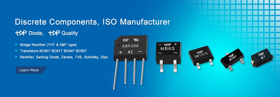
  topdiode TVS Diodes can fit a wide range of circuit protection applications but were primarily designed to protect I/O interfaces in telecommunication and industrial equipment, computers and consumer electronics.

  topdiode TVS Diode characteristics include:

  Low incremental surge resistance

  Unidirectional and Bidirectional polarities available

  Reverse standoff voltages range from 5 to 512V

  RoHS compliant–Matte Tin Pb-free plated

  Surface-mount power ratings from 400W to 5,000W

  Axial lead power ratings from 400W to 30,000W (30kW)

  High current protection available for 6kA and 10kA

  TVS Diode Glossary

  Clamping Device

  TVS is a clamping device that limits voltage spikes by low impedance avalanche breakdown of a rugged silicon PN junction. It is used to protect sensitive components from electrical overstress generated by induced lightning, inductive load switching and electrostatic discharge.

  Operating Temperature Range

  The minimum and maximum ambient operating temperature of the circuit in which a device will be applied. Operating temperature does not allow for the effects of adjacent components, this is a parameter the designer must take into consideration.

  Capacitance

  The property of a circuit element that permits it to store an electrical charge. In circuit protection, the off-state capacitance is typically measured at 1 MHz with a 2V bias applied.

  Reverse Standoff Voltage (VR)

  In the case of a uni-directional TVS diode, this is the maximum peak voltage that may be applied in the 'blocking direction' with no significant current flow. In the case of a bi-directional transient, it applies in either direction. It is the same definition as Maximum Off-state Voltage and Maximum Working Voltage.

  Breakdown Voltage (VBR)

  Breakdown voltage measured at a specified DC test current, typically 1mA. Usually a minimum and maximum is specified.

  Peak Pulse Current (IPP)

  Maximum pulse current which can be applied repetitively. Usually a 10x1000μs double exponential waveform, but can also be 8x20μs, if stated.

  Maximum Clamping Voltage (VC or VCI)

  Maximum voltage which can be measured across the protector when subjected to the Maximum Peak Pulse Current.

  Peak Pulse Power (PPP)

  Expressed in Watts or Kilowatts, for a 1ms exponential transient  it is IPP multiplied by VCL.


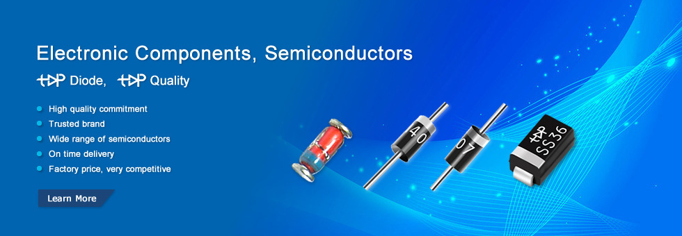
  P4KE6.8-P4KE440CA Axial Leaded 400W TVS Diode P4KE series

  P6KE6.8-P6KE440CA Axial Leaded 600W TVS Diodes P6KE series

  SMAJ5.0--SMAJ440CA Surface Mount TVS -Topdiode

  SMBJ5.0--SMBJ440CASurface Mount TVS -Topdiode

  SMCJ5.0-SMCJ440CA 1500W Suface Mount TVS Diode Topdiode

  TVS DIODE SD03, SD05, SD12-Topdiode

  5.0SMDJ12A-CA-5.0SMDJ170A-CA-Topdiode

  SMDJ5.0--SMDJ170CA-Surface Mount TVS -Topdiode

  ESD3Z_SERIES SOD-323-Topdiode

  SMA6J5.0--SMA6J200CA-Topdiode

  TVS Diodes P6SMB6.8-440ACA Topdiode

  TVS Diodes-P4SMA6.8-440ACA

  1.5KE6.8A-THRU-1.5KE600A-Topdiode


RoHS VS PB FREE

  RoHS VS PB FREE
  By Kelvin Tan
  What is RoHS? What is RoHS 2.0? What is RoHS 3.0?


  Directive 2011/65/EU was published in 2011 by the EU, which is known as RoHS-Recast or RoHS 2. RoHS 2 includes a CE-marking directive, with RoHS compliance now being required for CE marking of products. RoHS 2 also added Categories 8 and 9, and has additional compliance recordkeeping requirements.
  Directive 2015/863 is known as RoHS 3. RoHS 3 adds four additional restricted substances (phthalates) to the list of six.
  As now China's test lab does not have RoHS 3.0 test standard. So Topdiode and UF Capacitors only declare our products are RoHS 2.0 Compliant. We will update our certification according to latest regulations.
  RoHS Compliant for 2022
  Any business that sells applicable electrical or electronic products, equipment, sub-assemblies, cables, components, or spare parts directly to RoHS-directed countries, or sells to resellers, distributors or integrators that in turn sell products to these countries, is impacted if they utilize any of the restricted 10 substances.
  With the rapid spread of digitization, the world's production of electrical and electronic devices is exploding. Besides mobile devices, think about the coming wave of IoT, smart home assistants, robots, drones, 3D printers, and home medical devices to all corners of the planet...they are all regulated under RoHS.
  EU RoHS specifies maximum levels for the following 10 restricted substances. The first six applied to the original RoHS while the last four were added under RoHS 3, which took effect July 22, 2019.
  Cadmium (Cd): < 100 ppm
  Lead (Pb): < 1000 ppm
  Mercury (Hg): < 1000 ppm
  Hexavalent Chromium: (Cr VI) < 1000 ppm
  Polybrominated Biphenyls (PBB): < 1000 ppm
  Polybrominated Diphenyl Ethers (PBDE): < 1000 ppm
  Bis(2-Ethylhexyl) phthalate (DEHP): < 1000 ppm
  Benzyl butyl phthalate (BBP): < 1000 ppm
  Dibutyl phthalate (DBP): < 1000 ppm
  Diisobutyl phthalate (DIBP): < 1000 ppm
  About Lead-Free and RoHS
  In practice, RoHS-compliant is often equated with “lead-free”. However, this is a widespread mistake. The RoHS directive 2002/95/EC aims to minimize the use of hazardous substances (including, among others, lead), but it does not completely exclude a small percentage. One of the great obstacles in implementing the directive was the switchover to lead-free solder, because the limit values (0.1 per cent by weight of the inseparable components) do not admit a lead solder. This is probably the most important reason for the mix-up/equating that comes up again and again.
  Due to environmental concerns, the need for lead-free solutions in electronic components and systems is receiving increasing attention within the semiconductor and electronics industries.
  In a word, Lead Free and Pb Free is the same thing. Due to worldwide environmental restricted chemical and material (RCM) concerns, it was determined lead (Pb) as one of the major substances of concerns. Lead-free devices in electronic components and systems continues to receive significant attention within the semiconductor and electronics industry as a whole.
  Lead Free and Pb Free mean "No PB Process". PB Free and Lead-Free electronics components are definitely RoHS Compliant. But RoHS Compliant did not mean Pb Free of Lead Free.
  RoHS Compliant means lead <1000 PPM, and also accept exemption sometimes.
  Ps: Green products mean stricter: Lead (Pb): < 90 ppm
  Topdiode & UF Capacitors’ all components are RoHS Compliant. But not all our electronic components are PB Free or Lead-Free. If you require Lead-Free, pls check case by case.


Topdiode DB107S

Topdiode DB107S, Bridge Rectifier, 1A 1000V, 4-Pin DBS

  Manufacturer Topdiode part number: DB107S
  Gross weight: 0.378 g
  Bridge rectifier: single-phase; 1000V; If: 1A; SMT Bridge Rectifier,
  DB101S THRU DB107S  Single Phase, Glass Passivated Silicon Bridge Rectifier
  RoHS Reach compliant
  Topdiode L/T: 3-4 wks
  #Rectifler#Single-phasebridgetypefullycontrolledrectifiercircuit#Bridgerectifier#Theroleofthe rectifier#Electronic#rectifier##diode#shortage#chinasupply#maker#electroniccomponents#discrete#semiconductors#transistors#mosfet#diodes#chinabridgefactory#

we released 2015 Company Profile and UF Capacitors Catalogue 2015 Version

In July, we released 2015 Company Profile and UF Capacitors Catalogue 2015 Version.
You will find something interesting from these literature.
Please download from below link:  http://www.topdiode.com/Download.html 
www.topdiode.com
skype: Topdiode
Email: info@topdiode.com


Schottky diode


      Silicon carbide has a high thermal conductivity and temperature has little influence on its switching and thermal characteristics. With special packaging it is possible to have operating junction temperatures of over 500 K, which allows passive radiation cooling in aerospace applications.


      The Schottky diode (named after German physicist Walter H. Schottky; also known as hot carrier diode) is a semiconductor diode with a low forward voltage drop and a very fast switching action. The cat's-whisker detectors used in the early days of wireless can be considered primitive Schottky diodes.
When current flows through a diode there is a small voltage drop across the diode terminals. A normal silicon diode has a voltage drop between 0.6–1.7 volts, while a  

Email: info@topdiode.com  MSN: topdiode@gmail.com   Skype: topdiode  Website:www.topdiode.com

Lead time of SOT-23 small signal devices

Lead time of SOT-23 small signal devices
Some of our competitors are currently offering extreme long lead times on small signal devices, especially in SOT-23 package.

Topdiode can provide most of these parts within two to four wee

Book1.xlsx

Email: info@topdiode.com  MSN: topdiode@gmail.com   Skype: topdiode  Website:www.topdiode.com

Solder & Assembly Instructions

At the maximum lead wire temperature of 260°C, the soldering time must not exceed 10s. This assumes that the solder joint is spaced not less than 5mm from the case. If the joint is spaced less than 5mm, the soldering time must be reduced to 3s.
 Dip or Wave Soldering
Leaded devices: At the maximum soldering temperature of 260°C, the soldering time must not exceed 10s (or two times 5s at dual wave soldering). The soldering joint should be spaced not less than 1.5mm from the case.
 SMD devices: The soldering time must not exceed 10s at 260°C when the device is submerged completely into the solder. At dual wave soldering, this corresponds to two times 5s.
 Reflow Soldering
For reflow soldering of SMD devices the maximum admissible solder temperature is 260°C, for package outlines up to SMC/DO-214AB and peak time not exceeding 5s. Time above 255°C must not exceed 30s. For bigger case outlines, the solder temperature must be reduced.

Email: info@topdiode.com  MSN: topdiode@gmail.com   Skype: topdiode  Website:www.topdiode.com

What is a Switching Diode?

What is a Switching Diode?
Switching diodes are a single p-n diode in a discrete package. A switching diode provides the same functionality as a switch. It has high resistance below the specified applied voltage similar to an open switch, whereas above that voltage it changes in a sudden way to the low resistance of a closed switch. Switching diodes are used in devices such as ring modulation.

Types of Switching Diodes:
There are many different kinds of switching diodes. At Topdiode, we supply many of the most common types categorized by power dissipation, maximum reverse recovery time, maximum reverse voltage, maximum average forward current, packaging type and maximum peak current. The most common values for power dissipation are 200 mW, 250 mW, 350 mW and 500 mW. Please refer to our products page.

Applications for Switching Diodes:
The switching diode is the most basic function of almost every electronic application. Switching diodes are also used in high-speed rectifying applications, such as in radiofrequency receivers. Applications also include high-speed switching, general-purpose switching and reverse polarity protection in the consumer, automotive, and telecommunication industry.

Switching Diodes from Topdiode:


Small Signal Switching Diode

Average Forward Current


Peak Repetitive Reverse Voltage 

0.3A

 100V

1N4148 DO-35

LL4148 LL-34

1N4148W SOD-123

1N4148WS SOD-323


MCL4148 MicroMELF


Silicon Epitaxial Planar Switching Diode

Average Forward Current


BAV99 SOT-23

200mA

BAV70 SOT-23


What is a Bridge Rectifier?

What is a Bridge Rectifier?  

A bridge rectifier is an arrangement of four or more diodes in a bridge circuit configuration which provides the same output polarity for either input polarity. It is used for converting an alternating current (AC) input into a direct current (DC) output. A bridge rectifier provides full-wave rectification from a two-wire AC input, therefore resulting in lower weight and cost when compared to a rectifier with a 3-wire input from a transformer with a center-tapped secondary winding.
Types of Bridge Rectifiers
There are many different kinds of bridge rectifiers at Topdiode, we supply many of the most common types categorized by maximum average rectified current, maximum reverse voltage, maximum peak current, forward voltage, packaging type and maximum reverse current.
 The most common sizes for maximum average rectified current are 1A, 1.5 A, 4 A, 25 A and 35 A. We also carry bridge rectifiers with maximum average rectified current as high as 1000 A. Forward voltage can range from 450 mV to 1.1 kV, with the most common bridge rectifier semiconductor chips having a forward voltage of 1.1 V or 1 V.
Bridge Rectifiers from Topdiode.
 Applications for Bridge Rectifiers:
The primary application of bridge rectifiers is to transform an AC supply into DC power. All electronic devices require direct current, so bridge rectifiers are used inside the power supplies of almost all electronic equipment. Bridge rectifiers are also used for detecting the amplitude of modulated radio signals. The signal may be amplified before it is detected. If it is not, then a very low voltage drop diode or a diode biased with a fixed voltage must be used. Rectifiers are also used to supply polarized voltage for welding applications. Control of the output current is required in such circuits, and this may be achieved by replacing some of the diodes in a bridge rectifier with thyristors, which are diodes whose voltage output can be regulated by switching on and off with phase fired controllers.
Bridge Rectifier from Topdiode
Topdiode has a full selection of bridge rectifier chips that can be used to design a full wave bridge rectifier circuit, half wave rectifier or any other type of circuits that may require a bridge rectifier. 

Through-hole Bridge Rectifier (THT type)


Peak Repetitive Reverse Voltage   

50V

100V

200V

400V

600V

800V

1000V

Average Forward Current

0.5A


MB2M

MB4M

MB6M

MB8M

MB10M

1.0A

DB101

DB102

DB103

DB104

DB105

DB106

DB107

1.5A

DB151

DB152

DB153

DB154

DB155

DB156

DB157


D2SB20

D2SB40

D2SB60

D2SB80


2.0A

GBL201

GBL202

GBL203

GBL204

GBL205

GBL206

GBL207

KBP201

KBP202

KBP203

KBP204

KBP205

KBP206

KBP207

3.0A

KBP301

KBP302

KBP303

KBP304

KBP305

KBP306

KBP307

4.0A

GBL401

GBL402

GBL403

GBL404

GBL405

GBL406

GBL407

KBJ4A

KBJ4B

KBJ4D

KBJ4G

KBJ4J

KBJ4K

KBJ4M

D3SB05

D3SB10

D3SB20

D3SB40

D3SB60

D3SB80


GBU4A

GBU4B

GBU4D

GBU4G

GBU4J

GBU4K

GBU4M

6.0A

KBJ6A

KBJ6B

KBJ6D

KBJ6G

KBJ6J

KBJ6K

KBJ6M

GBU6A

GBU6B

GBU6D

GBU6G

GBU6J

GBU6K

GBU6M

8.0A

GBU8A

GBU8B

GBU8D

GBU8G

GBU8J

GBU8K

GBU8M

KBJ8A

KBJ8B

KBJ8D

KBJ8G

KBJ8J

KBJ8K

KBJ8M

10A

GBU10A

GBU10B

GBU10D

GBU10G

GBU10J

GBU10K

GBU10M

KBJ10A

KBJ10B

KBJ10D

KBJ10G

KBJ10J

KBJ10K

KBJ10M


Surface Mount Bridge Rectifier (SMT type)


Peak Repetitive Reverse Voltage

50V

100V

200V

400V

600V

800V

1000V

Average Forward Current

0.5A


MB2S

MB4S

MB6S

MB8S

MB10S

0.8A


ABS2

ABS4

ABS6

ABS8

ABS10

1.0A

DB101S

DB102S

DB103S

DB104S

DB105S

DB106S

DB107S

1.5A

DB151S

DB152S

DB153S

DB154S

DB155S

DB156S

DB157S

Email: info@topdiode.com  MSN: topdiode@gmail.com   Skype: topdiode  Website:www.topdiode.com  

What is a Zener Diode?

What is a Zener Diode?

Zener diodes are a special kind of diode which permits current to flow in the forward direction. What makes them different from other diodes is that Zener diodes will also allow current to flow in the reverse direction when the voltage is above a certain value. This breakdown voltage is known as the Zener voltage. In a standard diode, the Zener voltage is high, and the diode is permanently damaged if a reverse current above that value is allowed to pass through it. Zener diodes are designed in a way where the Zener voltage is a much lower value. There is a controlled breakdown which does not damage the diode when a reverse current above the Zener voltage passes through a Zener diode.
Types of Zener Diodes
There are many different kinds of Zener diodes. Topdiode supply many of the most common types categorized by power dissipation, nominal working voltage, forward (drive) current, forward voltage, packaging type and maximum reverse current. The most common values for nominal working voltage are 5.1 V, 5.6 V, 6.2 V, 12 V and 15 V. Forward (drive) current can have a range from 200 uA to 200 A, with the most common forward (drive) current being 10 mA or 200 mA.
Applications for Zener Diodes
Zener diodes can be found in several applications. Some of these are: voltage stabilizers or regulators (in shunt mode), surge suppressors for device protection, peak clippers, switching operations, reference elements and in meter protection applications. The constant reverse voltage of a Zener diode renders it a very useful component in regulating the output voltage against variations in the load resistance or variations in the input voltage from an unregulated power supply. The current through the Zener diode will change in order to keep the voltage within the threshold limits of Zener action and the maximum power that it can dissipate.

Zener Diodes in Topdiode

Zener Diode 

Power dissipation

P/N

Voltage Range

500mW,1/2W

BZX55C2V7~47V DO-35

2.7V~47V

500mW,1/2W

BZV55C2V4~47V LL-34

2.4V~47V

1000mW, 1W

1N4729A~1N4756A DO-41

3.3V~100V

500mW

DL4728A ~DL4764A LL-41

3.3V~100V

0.35W

BZX84C3V0-47V

3V0~47V


聚合内容